Because Your 450 Isn’t Fast Enough…
Story by Nick Stover
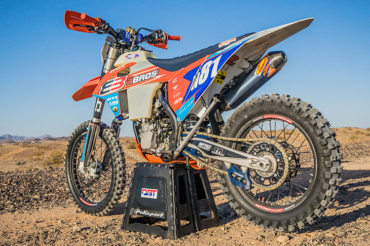
So you buy a new KTM 450XC-F or Husqvarna FX450 and you head out to the desert with some buddies. You start talking smack because you’ve got the biggest, baddest bike out there. Then you hit a dry lake bed and start clicking through the gears only to get to the top of 5th and reach for another– but there’s nothing there. Now your buddies on 350 XC-F’s are leaving you in the dust (we’ve tested this before and the 350XC-F with a 6th gear has a higher top speed than a 450XC-F with 5 gears). You may initially want to go to gearing and step up to a 14:45 sprocket combo to get that sweet speed you so crave, but first gear is all but useless for any tight trails.

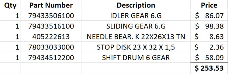
There is a solution, you just need to get into the cases and do some work. After you finish coughing up some sweet desert dust, you make the call to your local dealer and order up some parts to install that coveted 6th gear in your already blisteringly fast 450cc motor. With $300 in parts and a night after work (for a good mechanic), you too can have the triple digit rocketship that will show off its legs.
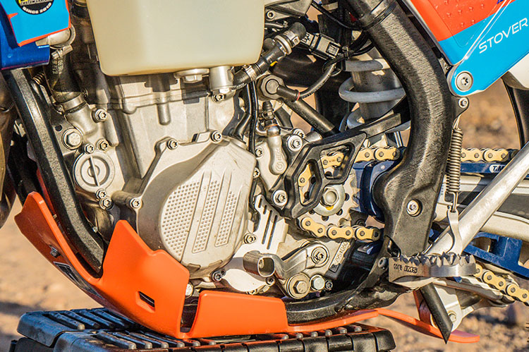
So where do you start? With the motor already out of the frame (refer to your owner’s manual for instructions on that), we’re going to detail all the specifics to make sure you too can feel like you’re the king of the dry lake bed.
*Prior to removing the motor out of the frame, we recommend taking a picture of the routing of the cables in addition to referring to your manual so that it is easy to place them back where they originally started. Also note that this is only a guideline, and any work should be performed based on the repair manual and by a professional…
Step-By-Step Instructions
STEP 1: Lock the motor in top dead center (TDC) –
STEP 2: Remove the ignition cover and spark plug.
STEP 3: Remove the bolt on the lower right hand side of the motor with a spacer on it.
STEP 4: Remove the spacer and reinstall the bolt by hand. Then rotate the motor using the flywheel until the bolt fits into the groove on the crank locking the motor and keeping it from rotating. The crankshaft is now locked in the desired TDC position.
STEP 5: Remove the camshaft.
STEP 6: Remove the valve cover as well as the valve chain tensioner located on the back of the cylinder.
STEP 7: Remove the clip holding the camshaft in place.
STEP 8: Pull the camshaft out of the holder and slip the timing chain off.
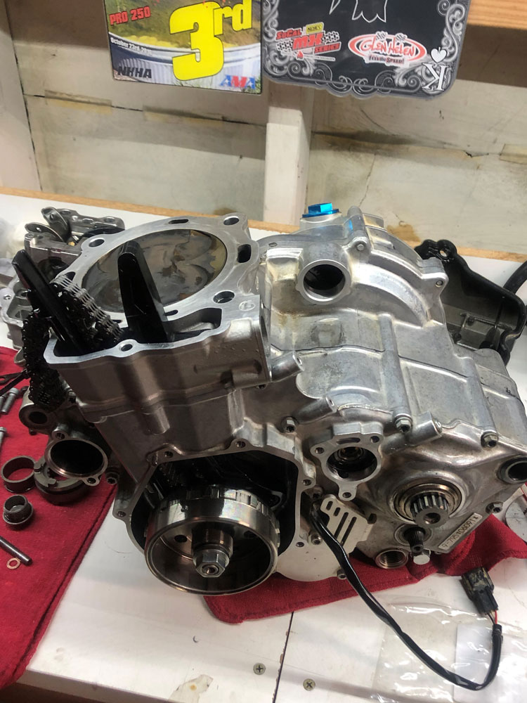
STEP 9: Remove the head and the cylinder – Undo the head bolts and lift the head off of the cylinder, followed by removing the cylinder.
RIGHT SIDE CASE
STEP 10: Remove the water pump cover and impeller.
STEP 11: Remove the right side cover.
STEP 12: Remove all clutch components including the clutch springs and plates. Follow this by removing the clutch nut, then remove the clutch hub, basket and bearings.
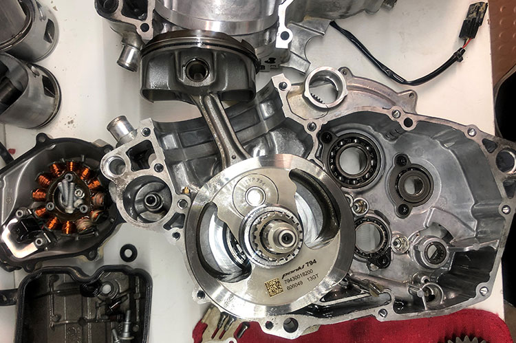
LEFT SIDE CASE
STEP 13: Remove the flywheel with a flywheel puller to expose the 8mm head bolts behind the flywheel.
STEP 14: Remove all the bolts on the left side case including the oil pump cover and the oil filter covers.
STEP 15: Pull the oil pump impeller and drive shaft out while making sure that the drive pin does not get lost.
STEP 16: Once all the bolts are removed lay the motor on its right side and tap on the tabs to separate the two sides, or use a case splitting tool.
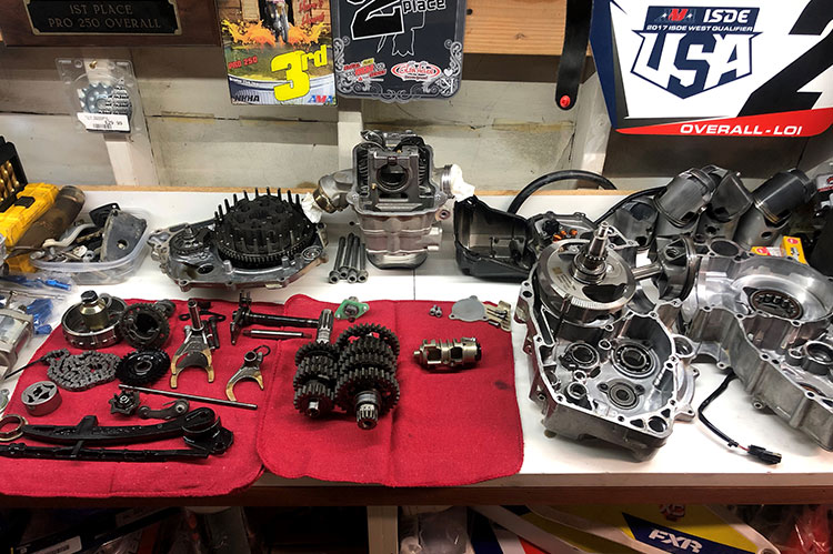
OUT WITH THE SLOW, IN WITH THE FAST
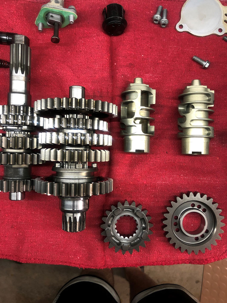
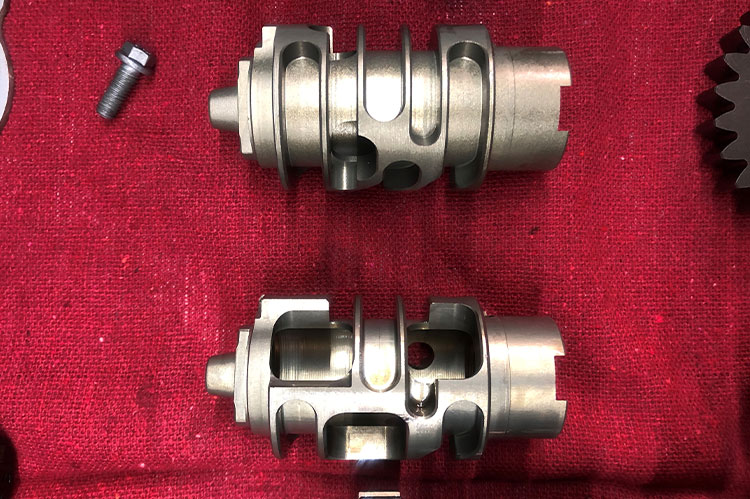
STEP 17: Once the transmission is exposed, remove the spacers that are on each shaft as well as the shifting drum. *Take special care to note the orientation of the shifting forks and the washers on either end of the transmission shafts.
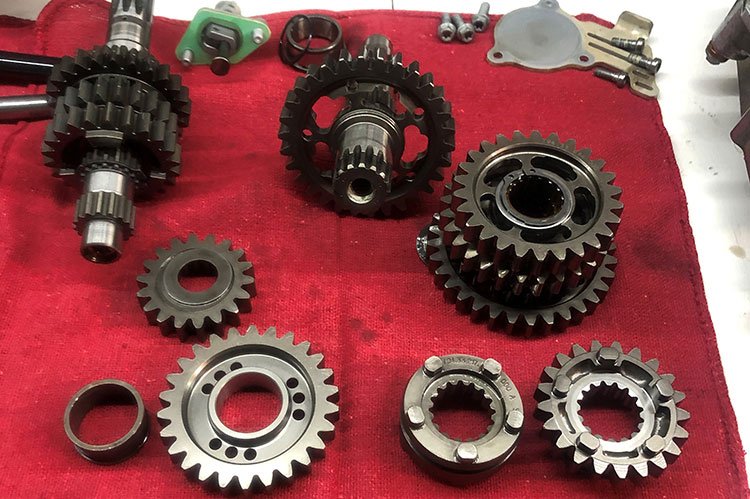
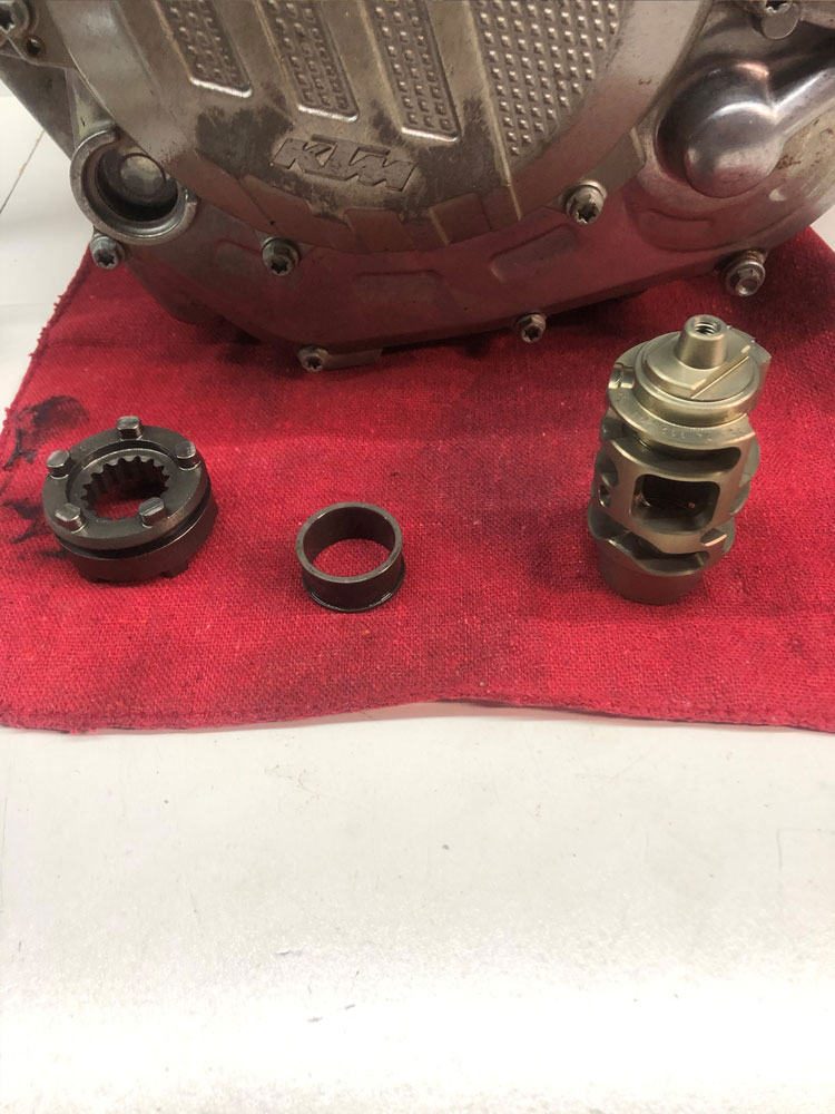
STEP 18: Locate the spacers on main and countershaft. Slide off the free wheeling spacer on the main shaft. Replace with the new 6th gear and bearing. On the main shaft you have to work from the clutch side and pull 2nd through 5th off in order to reach the spacer for 6th. Take special care to line up all the gears, washers, and circlips in the order and orientation that they came off the shaft. Replace the spacer with the new gear and reinstall everything that was removed from the shaft.
STEP 19: Take the two shafts and mesh the gears while placing them back into the clutch side of the cases. Once in place put the shifting forks back in their respective slots on the slider gears. Install the new shifting drum (threadlock recommended) on the shift drum locator. Swing the forks into their corresponding slots on the drum and insert the shifting fork sliders through the forks and into their recesses on the case.
STEP 20: Put a thin coat of gasket maker on the center case and slide the left case back into position. Reinstall the bolts holding the cases together.
STEP 21: After the cases are bolted together, reinstall the oil pump with special care on the drive pin that it sits in the right spot, as noted in Step 15, and does not wind up in one of the oil passages.
STEP 22: From there, everything is straight forward till you get to the counterbalancer/water pump. The water pump gear is marked to line up with the marks on the Primary gear located on the counterbalancer.
Once the clutch cover is back on you can move to the cylinder.
STEP 23: Installing the cylinder can be a pain. Getting the rings to compress while holding the cylinder in the right place is tricky as the rings are very thin and can easily get caught on the cylinder and bend or break. Sometimes it’s easier to remove the piston from the rod, slide it into the cylinder, then re-install the piston back onto the rod.
STEP 24: Once you torque the head bolts, you are set for the cam which again has marks for alignment. Match those up and throw in the last few bolts and you have a 100+ MPH motor.